
Project Vanara — Automotive IoT Crash Detection & Telemetry System
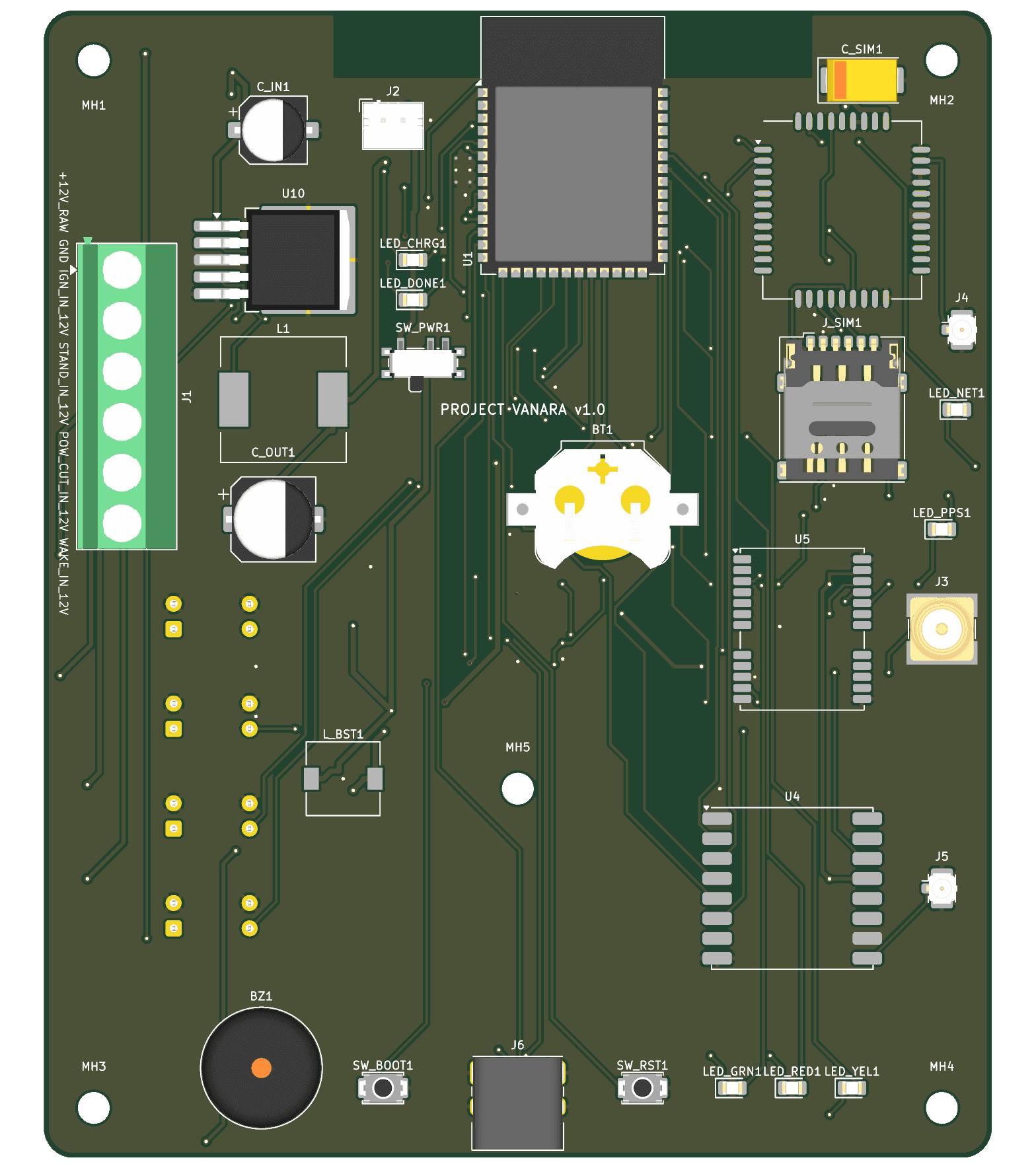
Engineered a ruggedized 4-layer automotive IoT crash detection and emergency telemetry PCB for motorcycles — packaging an ESP32-S3, 2A SIM800C GSM, NEO-M8N GPS, 433MHz Ra-02 LoRa, and a geometrically centered ADXL343 accelerometer within a 95 × 115 mm vibration-resistant footprint with complete 12V optoisolation, fail-safe battery power path, and zero DRC violations in KiCad 10.
What Makes This System Unique
Engineered a compact 95 × 115 mm 4-layer PCB with double-sided placement (29 top modules, 88 bottom SMD passives) to solve thermal & density bottlenecks
Placed ADXL343 3-axis crash accelerometer precisely at the geometric center (X=47.50, Y=57.50 mm) with internal M3 chassis mounting hole for pure inertial coupling
Multi-stage automotive power cascade: 12V input with SMBJ18CA TVS & PMOS reverse-polarity protection → LM2596 5V buck → TP4056 charger → MT3608 4.2V GSM burst boost → AP2112K 3.3V LDO
High-voltage motorcycle isolation: 4 optocoupled channels (Ignition, Side Stand, Power Cut, Wakeup) with 15V Zener clamps and reverse-blocking diodes
Multi-radio RF layout: Peripheral edge placement with dedicated copper keepout zones for 2.4GHz WiFi/BLE, GSM, GPS (SMA), and Sub-GHz LoRa (Ra-02)
Delivered complete KiCad 10.0.5 manufacturing package with ENIG finish, conformal coating clearances, full BOM, and verified 0 DRC / 0 ERC violations
Overview & Automotive Safety Brief
Project Vanara was conceived as a high-reliability automotive crash detection, theft prevention, and emergency telemetry unit for motorcycles. Operating in the harsh environment of two-wheelers demands resilience against violent mechanical vibrations, engine heat, electrical transients, water, and road dust. The system required integrating an ESP32-S3 microcontroller, cellular 2G/GPRS connectivity (SIM800C) with 2A burst capability, high-precision satellite positioning (u-blox NEO-M8N GPS), long-range Sub-GHz telemetry (Ai-Thinker Ra-02 433MHz LoRa), an ADXL343 accelerometer for impact detection, optical isolation for 12V vehicle battery signals, and an onboard rechargeable Li-Po battery backup.
The Electromechanical Dilemma: 120 Components vs. Motorcycle Packaging
The client initially specified a 2-layer PCB measuring roughly 80 × 100 mm. However, preliminary component mapping revealed an inventory of approximately 120 components, including large physical modules (ESP32-S3-WROOM-1, SIM800C, NEO-M8N, Ra-02, TO-263 LM2596 buck converter, 33uH power inductor, MKDS terminal blocks, SMA connector, and coin cell battery holder). SolveMpire conducted a feasibility and thermal safety evaluation and flagged critical constraints to the client: packing 120 components onto a 2-layer 80 × 100 mm board would severely compromise ground plane integrity, degrade RF antenna performance, and lead to localized thermal hotspots during 2A GSM transmission bursts and high-efficiency buck switching. Through engineering dialogue, SolveMpire negotiated an expanded form factor of 95 × 115 mm and transitioned the stackup to a 4-layer board with double-sided component placement: high-power active modules on the Top Layer, and compact SMD passives and isolation ICs on the Bottom Layer.
Geometric Center Sensor Placement & Vibration Mechanical Coupling
Accurate motorcycle crash and rollover detection requires measuring angular acceleration and impact forces without mechanical amplification or lever-arm distortions. SolveMpire positioned the ADXL343 3-axis accelerometer (U2) on the bottom layer exactly at the geometric center of the PCB (X = 47.50 mm, Y = 57.50 mm). To eliminate chassis flex and ensure rigid mechanical coupling, SolveMpire engineered a symmetrical mounting pattern consisting of four M3 corner mounting holes (5.0 mm offsets with 3.2 mm drill / 6.0 mm pads) plus a critical internal support mounting hole MH5 located at (X = 47.50 mm, Y = 78.00 mm). This mechanical anchoring rigidly couples the accelerometer to the motorcycle frame while dampening resonant board vibrations.
Multi-Stage Automotive Power Architecture & Fail-Safe Battery Switchover
Motorcycle electrical systems are notorious for violent voltage transients, inductive kicks from the starter motor, and alternator load dump surges. SolveMpire engineered a robust multi-stage power topology: • Input Protection: The 12V raw vehicle input passes through an SMBJ18CA bidirectional TVS diode to clamp automotive transients, paired with a P-channel MOSFET (SI2301) and 12V Zener gate clamp (BZT52C12) for zero-loss reverse-polarity protection. • Step-Down Buck Converter: A high-efficiency LM2596S-ADJ regulator (TO-263-5) steps the noisy 9V–16V vehicle input down to a stabilized 5.0V / 3A rail, buffered by a 33uH high-current inductor and 330uF low-ESR output capacitor. • Battery Charging: During schematic review, SolveMpire caught a severe flaw in the client's original draft where 12V was wired directly to a TP4056 charger (which has an 8V absolute maximum rating). SolveMpire routed the regulated 5.0V buck rail into the TP4056 (SOIC-8-EP with thermal vias) to safely charge an onboard 3.7V Li-Po battery via a JST-PH connector, complete with Red (charging) and Green (standby) status LEDs. • Master Cutoff & GSM Boost: An onboard SPDT slide switch provides manual battery disconnection. When operating on battery, an MT3608 high-frequency boost converter steps the 3.7V battery voltage up to a rock-solid 4.2V rail. This dedicated rail feeds the SIM800C module, buffered by a 100uF tantalum capacitor (C_SIM1) to seamlessly absorb 2.0A GSM transmission bursts without causing system brownout. • Ultra-Low-Noise 3.3V Logic: The 4.2V rail feeds an AP2112K-3.3 linear LDO, supplying ripple-free 3.3V power to the ESP32-S3, GPS engine, LoRa transceiver, and digital sensors.
High-Voltage Vehicle Optical Isolation (4 Independent Channels)
Motorcycle sensor lines (Ignition, Side Stand, Main Power Cut, and External Wakeup) carry raw 12V signals exposed to electromagnetic noise from spark ignition coils and alternator ripple. SolveMpire integrated 4 independent PC817 optocouplers (U6, U7, U8, U9) aligned neatly along the board edge on the bottom layer. The 12V inputs are conditioned with precision current-limiting series resistors, 15V Zener protective clamp diodes (BZT52C15), and 1N4148 reverse diodes to protect the infrared emitting diodes against reverse breakdown and overvoltage spikes. The phototransistor collector outputs deliver pristine, optically isolated 3.3V logic signals directly to ESP32-S3 GPIOs (GPIO8, GPIO9, GPIO13, GPIO10) with internal pull-ups, creating a galvanic barrier that shields the core processor from vehicle ground bounce.
Multi-Radio RF Coexistence & Antenna Keepout Engineering
Project Vanara houses four wireless transceivers on a single PCB: 2.4GHz Wi-Fi / BLE 5.0 (ESP32-S3), 2G/GPRS Cellular (SIM800C), Sub-GHz LoRa (Ra-02 433MHz), and GNSS Satellite Navigation (u-blox NEO-M8N). To eliminate mutual RF interference and desensitization, SolveMpire arranged all radio modules around the outer perimeter of the PCB: • The ESP32-S3-WROOM-1 is placed along the top edge, featuring a strict copper keep-out zone beneath its integrated PCB antenna across all 4 copper layers. • The SIM800C is positioned on the top-right perimeter with a dedicated U.FL connector and microstrip RF trace routed with 50-ohm controlled geometry. • The u-blox NEO-M8N GPS module sits on the right edge with an external SMA connector (J3) directly adjacent to its RF_IN pin to minimize trace loss. • The Ra-02 LoRa module occupies the lower-right edge with its own dedicated U.FL connector (J5). • Layer 2 is dedicated as an uninterrupted, solid ground plane, providing low-impedance return paths and electromagnetic shielding across all RF sections.
Chip-Down Interface Integration: SIM, PWRKEY & GPS RTC Hot-Start
To meet automotive reliability standards, modular breakout boards were replaced with production chip-down implementations: • SIM Card Interface: An onboard hinged Nano-SIM card holder (NSIM-2-C) was integrated with an SMF05C multi-channel TVS diode array, protecting SIM clock, data, and reset lines against electrostatic discharge during card insertion. • Software PWRKEY Management: An MMBT3904 NPN transistor driver circuit was connected to the SIM800C PWRKEY pin, allowing ESP32-S3 firmware to autonomously power-cycle the cellular module, recover from network timeouts, or power down the modem during deep sleep. • GPS Instant Hot-Start: A Keystone CR1220 coin cell retainer (BT1) was integrated and paired with a BAT54C dual Schottky steering diode. This provides continuous backup voltage to the NEO-M8N V_BCKP pin from either the main 3.3V rail or the coin cell, preserving ephemeris, almanac, and RTC time data to slash Time-To-First-Fix (TTFF) from 27 seconds (cold start) to under 1 second (hot start) upon vehicle ignition. • Configuration UART: Bidirectional UART lines (GPS_TX on GPIO15, GPS_RX on GPIO18) were routed to enable firmware dynamic configuration of NMEA update rates (up to 10Hz) and satellite constellations.
KiCad 10 DFM Hardening, Zero-Violation DRC & Manufacturing Handover
The production package was engineered in KiCad 10.0.5 and subjected to rigorous Design Rule Checking (DRC) and Electrical Rules Checking (ERC): • The initial client layout contained 201 DRC errors, 460 DRC warnings, and 198 schematic-to-PCB parity issues. SolveMpire fully re-architected the layout, resolving 100% of anomalies to achieve a flawless 0 DRC / 0 ERC verification report. • Custom footprint variants were created with 0.3 mm thermal drill arrays under the ESP32-S3 and TP4056 exposed ground pads, optimizing thermal dissipation through the inner ground plane without solder-wicking defects. • The manufacturing package was delivered with separate plated (PTH) and non-plated (NPTH) Excellon drill files, Gerber X2 fabrication archives, top/bottom CPL pick-and-place files, and a comprehensive 9-column BOM. • The board specification mandates an Electroless Nickel Immersion Gold (ENIG) surface finish for superior contact reliability and flat pad co-planarity, alongside strict silkscreen clearances for automotive-grade conformal coating application.
Validated Performance In The Real World
- Engineered a high-density 4-layer automotive PCB (95 × 115 mm) integrating 117 components across 4 wireless protocols and complete 12V vehicle isolation
- Centered ADXL343 crash sensor and 5-point M3 mounting pattern eliminate false positives and mechanical vibration resonance
- Fail-safe multi-stage power path: TVS + reverse PMOS → 5V buck → Li-Po charger → 4.2V boost (2A GSM) → 3.3V low-noise LDO
- Eliminated 100% of DRC/ERC anomalies (from 661 baseline errors/warnings to 0 violations in KiCad 10.0.5)
- Delivered comprehensive production package: Gerber X2, Excellon drill files, pick-and-place CPL, verified BOM, and ENIG/conformal coating specs